15 Watt Series Switching Adaptor (For Battery Charger and Home Applicance)
Shape and Dimensions
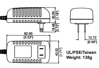
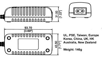
1)UL,PSE Case, Wall Mount Style
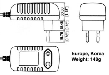
2)CE, Korea Case, Wall Mount Style
3)Universal Case, Desktop Style
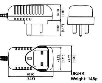
4)UK,HK Case, Wall Mount Style
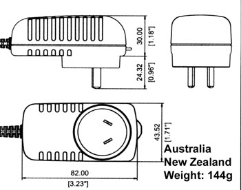
5)Australia, New Zealand Case, Style
Main Characteristics
Product Highlight
- Complete, inexpensive, self-contained regulated power source
- Universal input voltage 100~240 VAC 50/60HZ
- Super power supply, fixed frequency control circuit guarantees stable,recharging of sealed acid batteries that are used in electrically powered scooters, motorcycles, and much more
- Optomum control for maximum battery capacity and long life cycle, 3 stage charging system.(constant current, constant voltage, maintenace charge) for rapid full charge
- Ultra safe design, all with their respective safety approvals.
- Ultra low no-load/standby power consumption, meeting EC 2005 green power requirements.
- Light, sleek, and compact design
- Direct LED control output displays charge status and fault conditions and fault conditions:
Red light: Power On
Orange light: Charging
Green light: Charged- High efficiency circuitry that generates little heat
- Built in EMI filter.
Built-in Features and protections
- Different output voltage selections: 2.8-24 Vdc.
- Short circuit protection.
- Over voltage protection.
- Over current protection.
- Thermal shutdown capability.
Reliability
- Burn-in: 100% full load ,40+/-5degree C, 4Hrs min.
- Leakage Current: Class two: 0.25mA max. at 254Vac. Class one: 0.75mA max. at 254Vac.
- Withstanding Voltage:(between primary & secondary) Class two:3000Vac I minute 10mA max., Class one: 1500Vac 1 minute 10mA max.,
- MTBF: meet MIL-HDBK-217F over 50K hours,full load, 25 degree C
Safety approvals
- UL1310
- EN60335
- CE
Emissions
- FCC Part 15 class B
- EN55022 class B
Immunity
- EN61000-3-2:2000
- EN61000-3-3: 1995+A1
Schematic Drawings
Electrical specifications
Description
Symbol
Min
Typ
Max
Units
Comment
Input
Voltage
VIN
90
120/240
264
VAC
�� Frequency
FLINE
47
50/60
63
Hz
�� No-load Input
Power(230VAC)�� �� �� 0.75
W
�� Efficiency
�� 70
�� %
�� Inrush
Current(240Vac)
I��
40��
A
Cold 25 degree CEnvironmental
Operating
TemperatureT
0
/
40
Degree
C
Free convection, Sea level
Non-operating
T
-20
/
80
Degree
CFree convection, Sea level
Operating humidity
T
10
/
90
%RH
Non condensing
Non-operating
humidityT
10
/ 90
%RH
Non condensing
Typical model list
INPUT
CONDITIONDC OUTPUT
VOLTAGE
DC OUTPUT
CURRENT
OUTPUT
VOLTAGE
PRECISIONRIPPLE
&
NOISESREGULATION
MAXIMUM
OUTPUTPOWERLINE LOAD �� 1
21-24V
0-0.71A
5%
400mY
+/-2%
+/-5%
15W
�� 2
1 6V-20V
0-0.84A
5%
400mY
+/-2%
+/-5%
15W
Input voltage:
3
10-15V
0-1.50A
5%
400mV
+/-2%
+/-5%
15W
90-264Vac
4
9.4-9..9V
0-1.60A
5%
400mV
+/-2%
+/-5%
15W
Frequency:
5
8.8-8.3V
0-1.70A
5%
400mV
+/-2%
+/-5%
15W
47-63Hz
6
8.2-8.7V
0-1.83A
5%
400mY
+/-2%
+/-5%
15W
Input current:
7
7.6-8.1V
0-1.97A
5%
400mV
+/-2%
+/-5%
15W
0.4A
8
7.0-7.5V
0-2A
5%
400mV
+/-2%
+/-5%
15W
�� 9
6.4-6.9V
0-2A
5%
400mV
+/-2%
+/-5%
13.8W
�� 10
5.8-6.3V
0-2A
5%
400mV
+/-2%
+/-5%
12.6W
�� 11
5.0-5.7V
0-2A
5%
400mY
+/-2%
+/-5%
11.4W
Remark: Refer to ripple and noise
1. Measurements shall be made with an oscilloscope with 20MHz bandwidth.
2. Outputs shall be bypassed at the connector with a 0.1 uF ceramic disk capacitor and
a 10uF electrolytic capacitor to simulate system loading.Standard Product
MODEL
INPUT
VOLTAGE
INPUT
FREQUENCY
BATTERY
SPECIFICATION
DC OUTPUT
CURRENT
DESIRED
FLOAT
VO LTAGE
CHARGING VOLTAGEKSC FD0600150W1ZZ
KSCFD0600150T1M2
90-264V
50/60Hz
6V/17AH
1.5A
6.8V
7.4VKSCFD1200100W1ZZ
KSCFD1200100T1M290-264V
50/60Hz
1 2V/1 7AH
1.0A
13.7V
14.7V
KSCFD2400050 W1ZZ
KSCFD2400050 T1 M290-264V
50/60Hz
24V/17AH
0.5A
27.4V
29.4V
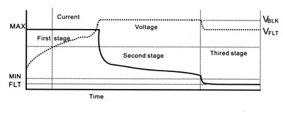
Charging Characteristics
1 .A state diagram for sealed-acid
battery harger is shown in the left This charger,called a dual level
float charger, has three status,
a high current bulk charge state,
an over-charge state,and float charge state.
2.In the first state,the charger acts like a current source providing a constant charge rate at Imax, the charger monitor the battery voltage and as it reaches transiton threshold,Va,the charger begins its second state.3.In the second state,the charger regulates the battery at an elevated voltage, Vb,until the charger rate drops to a specified transition current, Imin,, When the current tapers
to Imin,the capacity of the cell should be at nearly 100%.
4.In the third state,the charger maintains a precision voltage across the battery
to optimize stand-by life.
All the rights reserved for Wintach Electronics Co., Limited