25 Watt Series Switching Adaptor
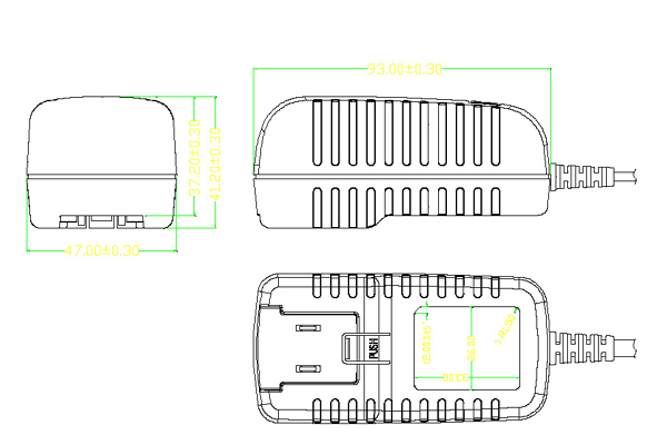
Shape and dimensions:
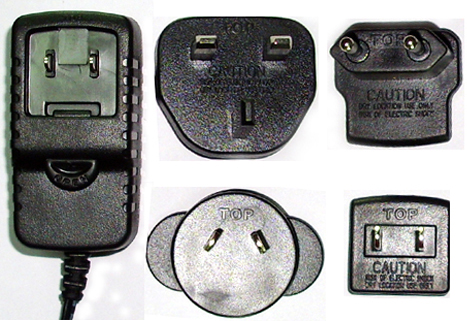
1)UL,PSE Case, Wall Mount Style
2)Europe, Korea Case, Wall Mount Style
3)Universal Case, Desktop Style
4)UK,HK Case, Wall Mount Style
5)Australia, New Zealand Case, Wall Mount Style
6)Interchangeable plugs Style
Main Characteristics
Product Highlight
- Complete, inexpensive, self-contained regulated power source
for use in charging cell Lithium-ion and/or NiCd or NiMH batteries- Super power supply, fixed frequency control circuit guarantees Stable, long-lasting output required by any mobile electronics, such as Mobile phones, Walkie-Talkie, PDA, Digital camera, CD/MP3 player,CDMA, digital players, testing machines, HUB, modem, scanners, printers and much more.
- Ultra safe design, all with their respective safety approvals.
- Ultra low no-load/standby power consumption, meeting EC 2005 green power requirements.
- Light, sleek, and compact design
- On-line LED power indicator , (optional)
- High efficiency circuitry that generates little heat
- Built in EMI filter.
Built-in Features and protections
- Short circuit protection.
- Over voltage protection.
- Over current protection.
- Thermal shutdown capability.
Reliability
- Burn-in: 100% full load ,40+/-5degree C, 4Hrs min.
- Leakage Current: Class two: 0.25mA max. at 254Vac.
- Withstanding Voltage:(between primary & secondary) 3000Vac I minute 10mA max., Class one: 1500Vac 1 minute 10mA max.,
- MTBF: meet MIL-HDBK-217F over 50K hours,full load, 25 degree C
Safety approvals
- UL60950 3rd edition CAN/CSA C22.2 NO.60950
- EN60950:2000
- CE(Low Voltage Directive)
- AS/NZS 60950:2000 A1
- PSE IEC60950
- GB4943-2001
Emissions
- FCC Part 15 class B
- EN55022 class B
- AS/NZS3548,AS/NZS4251.1 class B
- VCCI class B
- CNS 13438 class B
- GB9254-1998/G B 17625.1-2003
- ClSPR22 class B
Immunity
- EN55024/A 1:2001
- Electrostatic discharge:61000-4-2
- Radiated electromagnetic fields:61000-4-3
- Fast transients(burst):61000-4-4
- Surge transients:61000-4-5
- Conducted disturbance:61000-4-6
- Voltage dips, interruptions & variations:61000-4-11
Schematic Drawings
Standard Product Specifications
Description Min. Typical Max. Comment Input Voltage(V) 90 120 264 Fequency(Hz) 47 50/60 63 No-load power loss(W) 0.3 Output Output voltage(V) 2.8 12 24 Output current(mA) 10 4000mA Output Ripple Voltage(mV) 40 100 200mV 20MHz Bandwidth Total output power Continuous output power 0.14 30 Peak output power 30 Efficiency (%) 60 70 Environmental Operating temperature 0°C 40°C Fee convection, Non-operating temperature -20°C 80°C Operating humidity 10°C 90°C Non condensing Non-operating humidity 10°C 90°C Non condensing Typical Model List
INPUT
CONDITION��DC OUTPUT
VOLTAGE
DC OUTPUT
CURRENT
OUTPUT
VOLTAGE
PRECISIONRIPPLE
&
NOISESREGULATION
MAXIMUM
OUTPUT
POWER
LINE
LOAD
������ Input voltage:
90-264VacFrequency:
47-63HzInputcurrent:
0.6A��������1
31.5 -48.0V
0.02-0.95A
5%
150mY
+/-1%
+/-5%
30W
2
30.5 -31.0V
0.025-0.98A
5%
150mY
+/-1%
+/-5%
30W
3
22.1-30.0V
0.03-1.36A
5%
100mV
+/-1%
+/-5%
30W
4
18.2-22.0V
0.035-1.67A
5%
100rev
+/-1%
+/-5%
30W
5
12.0-17.9V
0.04-2.5A
5%
100mY
+/-1%
+/-5%
30W
6
11.1-11.9V
0.04-2.25A
5%
100mY
+/-1%
+/-5%
25W
7
9.1-10.0V
0.05-2.75A
5%
100mV
+/-1%
+/-5%
25W
8
8.1-9.0V
0.055-3.09A
5%
100mY
+/-1%
+/-5%
25W
9
7.0-8.0V
0.06-3.57A
5%
100mY
+/-1%
+/-5%
25W
10
6.0-6.9V
0.07-4.1A
6%
100mV
+/-1%
+/-5%
25W
11
4.1-6.0V
0.08-4.0A
6%
100mY
+/-1%
+/-5%
24W
12
3.0-4.0V
0.1-4.0A
6%
100mV
+/-1%
+/-5%
16W
Remark: Refer to ripple and noise
1. Measurements shall be made with an oscilloscope with 20MHz bandwidth.
2. Outputs shall be bypassed at the connector with a 0.1 uF ceramic disk capacitor and
a 10uF electrolytic capacitor to simulate system loading.
All the rights reserved for Wintach Electronics Co., Limited